Lecture 07 - Layered Protocols
Summary
In this lecture, we put (wired) communication links in the context of network protocols. Within the framework of OSI layered protocol architecture, we highlight TCP and UDP transport layer protocols, the IP network layer protocol, and Ethernet medium-access and physical-layer protocols.
Motivation in Course Context
The last lecture provided just enough introduction for us to imagine point-to-point digital communication over wired media. As we proceed, we will learn the technologies that allow us replace wired links with wireless links.
Before doing so, we take the opportunity to summarize network protocol architectures in which both wired and wireless links function.
Outline
OSI Layered Protocol Stack
Nesting Packets and Overhead
Examples: TCP and UDP, IP, Ethernet
Error Detection
Home Network Motivation

Open Systems Interconnection (OSI) Model
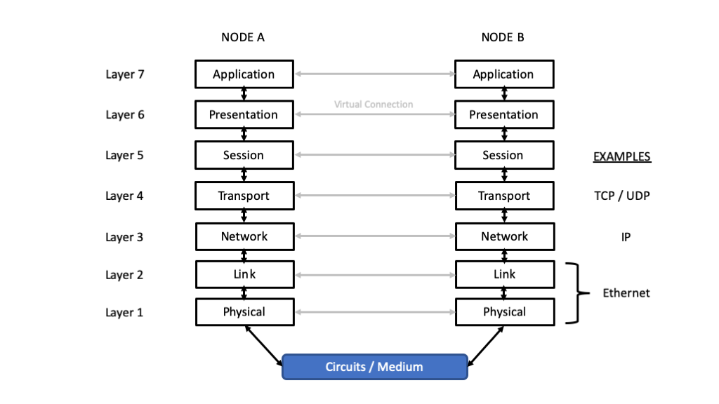
Many network protocol architectures can be cast into a model called the Open Systems Interconnection (OSI) model. This modeled is illustrated in Figure 2.

Layer Functions
Application Layer - High-level APIs, including resource sharing, remote file access
Presentation Layer - Translation of data between a networking service and an application; including character encoding, data compression and encryption/decryption
Session Layer - Managing communication sessions, i.e., continuous exchange of information in the form of multiple back-and-forth transmissions between two nodes
Transport Layer - Reliable transmission of data segments between points on a network, including segmentation, acknowledgement and multiplexing
Network Layer - Structuring and managing a multi-node network, including addressing, routing and traffic control
Link Layer - Reliable transmission of data frames between two nodes connected by a physical layer
Physical Layer - Transmission and reception of raw bit streams over a physical medium
Standards
The OSI model became an international standard through the efforts of the International Standards Organization (ISO) and the International Telecommunications Union (ITU):
- ISO 7498 https://www.iso.org/standard/20269.html
- ITU T X.200 https://www.itu.int/rec/T-REC-X.200/en
Nesting Packets
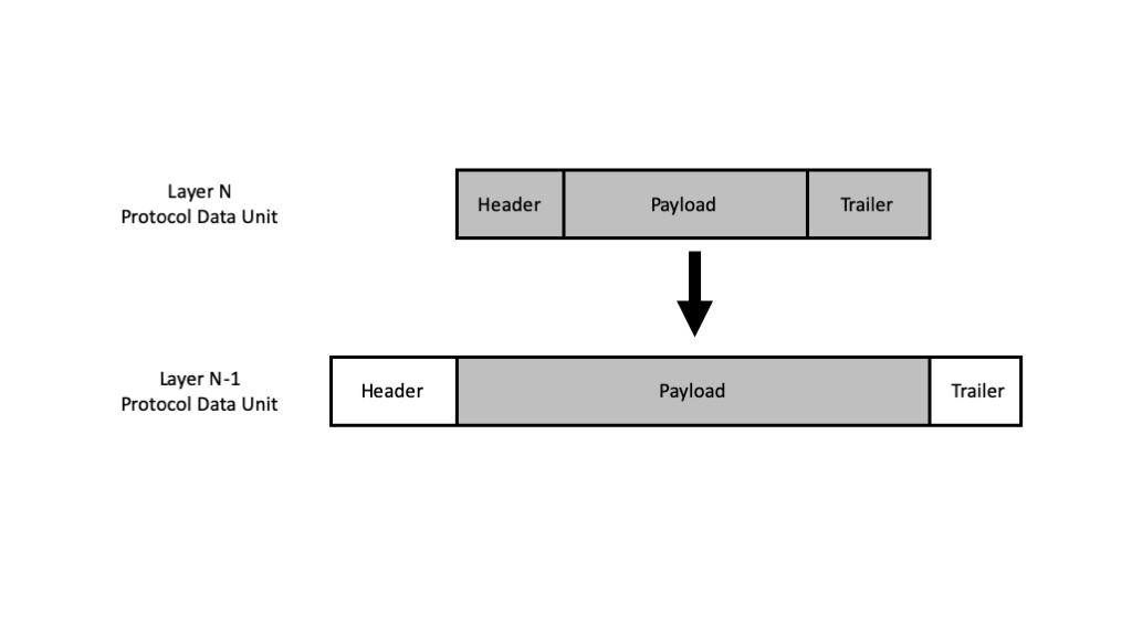
Figure 3 illustrates how packets are nested as we move down a layered protocol stack.

In OSI terminology, a complete packet formed at a given layer is called a protocol data unit (PDU). A Layer \(n\) PDU that is passed in and out of Layer \(n-1\) is called service data unit (SDU) in the context of Layer \(n-1\).
Now consider one Application Layer PDU as it is passed down the stack. Each of the lower layers adds its own header and potentially trailer to the SDU it receives from the layer above. In some cases, an SDU is fragmented into multple PDUs by an intermediate layer, so that additional sequencing information must be added. By the time the Application Layer PDU is transmitted through the medium, it can be wrapped in a significant number of bits that are not data. The non-data portion of the transmission is referred to protocol information or overhead.
Examples
Transport Layer
Transmission Control Protocol (TCP) https://en.wikipedia.org/wiki/Transmission_Control_Protocol
- Connection-Oriented, Host-to-Host, Two-Way
- Retransmissions
- Reordering
- Flow Control
- Header: 20 - 60 bytes
- Payload: Default Maximum Segment Size (MSS) 536 bytes using IPv4
User Datagram Protocol (UDP) https://en.wikipedia.org/wiki/User_Datagram_Protocol
- Connectionless, One-Way
- No retransmissions or reordering
- No Flow Control
- Header: 8 bytes
- Payload: Maximum size 65,507 bytes using IPv4
Network Layer
Internet Protocol (IP) - https://en.wikipedia.org/wiki/IPv4
- Routing Between Nodes
- Fragmentation and Reassambly
- Header: 5-60 bytes
- Payload: Maximum 65,530 bytes
Link and Physical Layer
Ethernet: https://en.wikipedia.org/wiki/Ethernet_frame
- Header: 23-27 bytes
- Payload: 46-1500 bytes
- Trailer: 16 bytes (4 byte Frame Check Sequence, 12 byte gap)
Common Header / Trailer Fields
Based upon these examples, we see that packet headers and trailers has some common fields that include
Addresses (Source, Destination)
Packet Length
Sequence Number
Error Detection Bits / Checksum
Acknowledgements
Layer-Specific Parameters and Protocol Information
Error Detection
As we have seen, many packet formats include protocol information that allows a receiving layer to verify the packet before extracting the SDU to delivery for the next layer.
Some high-level error detection mechanisms include:
Formating constraints on the fields themselves, e.g., if the protocol says only particular values of fields are allowed
Length constraints, e.g., comparing the received packet length to length information included in the header or trailer
Sequence numbers, e.g., keeping track of received seqeuence numbers and identifyin when a packet is lost
In the remainder of this section, we discuss specific fields of bits that are added to “check” the integrity of the payload as well as the packet as a whole.
Binary Parity Check
To simply illustrate the idea of check bits and error detection, consider a binary field of \(k\) data bits denoted \(b_1,b_2,\ldots,b_k\). Now suppose that we compute the modulo-2 sum, or exclusive or, of all the data bits \[c = b_1 \oplus b_2 \oplus \cdots \oplus b_k\]
If \(c=1\), the data bits must have an odd number of \(1\)’s, which we call odd parity. If \(c=0\), the data bits must have an even number of \(1\)’s, which we call even parity. Regardless of the parity of the data bits, the concatenation of the data bits and the check bit will have even parity.
Now consider transmitting the concatenation of the data bits and the check bits over a communication link, and let \(\tilde{b}_i\), \(i=1,2,\ldots,k\) and \(\tilde{c}\) denote the received bits. If \[ \tilde{c} \neq \tilde{b}_1 \oplus \tilde{b}_2 \oplus \cdots \oplus \tilde{b}_k \] we can conclude in the receiving layer that errors occurred.
Checksum
Instead of adding the individual bits in a field modulo-2, we can break a field into bytes and add them up modulo-256 (or modulo-2 at the bit level) to produce 8 check bits. Or we can break the field up into 16-bit words and add them up module \(2^{16}\) (or modulo-2 at the bit level) to produce 16 check bits. We refer to such an approach broadly as a checksum, with the understanding that there are different variations on computing such checksums.
For example, the IP Header Checksum is computed as the “1’s complement of the 1’s complement sum of the header treated as 16-bit words.”
Cyclic Redundancy Check (CRC)
A cyclic redundancy check (CRC) adds a fixed number of check symbols to a block of data using a particular kind of error-detecting code called a systematic, cyclic code. This can be viewed as multiple parity check bits computed in a certain way.
In particular, the CRC represents the remainder of polynomial division in a finite field, often \(\mathrm{GF}(2)\) with modulo-2 addition and multiplication, between the data represented as a polynomial and a generator polynominal for the code.
Typically an \(n\)-bit CRC applied to a data block of arbitrary length will detect any single error burst not longer than \(n\) bits, and the fraction of all longer error bursts that it will detect is \((1 − 2^{−n})\). It cannot detect errors corresponding to two data polynomials that have the same remainder after long division by the generator polynomial.
The simplest error-detection system, the parity bit, is in fact a 1-bit CRC: it uses the generator polynomial \(x + 1\) (two terms), and has the name CRC-1.
The standard 32-bit CRC uses generator polynomial \[ x^{32} + x^{26} + x^{23} + x^{22} + x^{16} + x^{12} + x^{11} + x^{10} + x^{8} + x^{7} + x^{5} + x^{4} + x^{2} + x + 1 \]
Additional information and examples are available at: https://en.wikipedia.org/wiki/Cyclic_redundancy_check
